Puzzle 69 of 100

A set and reset latch

Goal

Make Q go high when S is high and low when R is high, and keep its level while S and R are both low.

Die
13 by 12 squares
Layers
Metal, Polysilicon, Contact, N active, P active, N well, Metal 2, Via
Inputs
S, R
Output
Q
Supply
VDD
Ground
GND

Go to the solution

New in this puzzle

Gates that feed each other

Two NOR gates whose outputs drive each other's inputs form a loop. Once one output is high and the other low, the loop keeps them that way.

Set, reset, and hold

A high S makes Q high, and a high R makes Q low. While both are low, Q keeps the level it was given last. A circuit that holds a level this way is a latch.

Guide

  1. Join Q to the free input of the right NOR gate: paint polysilicon and a contact on the outlined square beside its gate, and metal from Q to the contact.
  2. Join QN, the output of the right gate, back to the free input of the left gate in the same way. Metal crosses the polysilicon line without joining it.

Hint

  1. Hint 1 of 3

    Join the output of each NOR gate to the free input of the other. While S and R are low, each gate holds the other's output where it is, so the pair keeps its level.

  2. Hint 2 of 3

    Look between the two gates. The marked square is on one possible feedback route.

  3. Hint 3 of 3

    Connect each gate output to one input of the other gate. Keep S and R on the remaining inputs. Watch Q after the input pulses end.

These hints describe one valid approach. Other drawings can pass.

Solution

This is the game's reference drawing for the puzzle. It meets the goal and passes the design rules. Other drawings can pass as well.
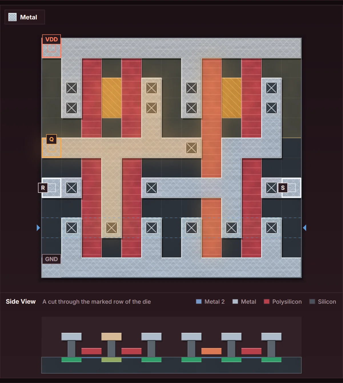
Top View of the solved die for puzzle 69, A set and reset latch, with the Side View below it.
Top View of the solved die, captured from the game. Paths that carry a high level at the moment shown are lit. The Side View below cuts through the row between the dashed lines.
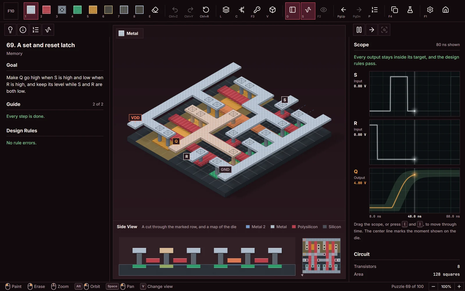
The game window in Isometric View with the solved die for puzzle 69, A set and reset latch, the guide, and the scope.
The whole game window in Isometric View. The scope on the right compares each output with its target band, and the message above it confirms that the drawing passes.
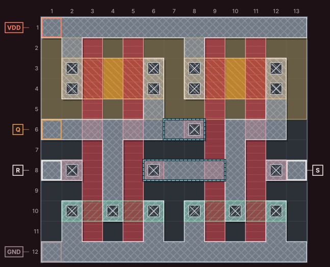
Solution drawing for puzzle 69, A set and reset latch, drawn on a numbered grid with every layer in its game color and pattern.
The solution on the grid. Squares are numbered from the top left corner, so you can count them. The dashed outline marks the squares you draw, change, or erase; the rest is drawn when the puzzle opens.

Legend

  • Metal73 squares
  • Polysilicon44 squares
  • Contact18 squares
  • N active10 squares
  • P active20 squares
  • N well52 squares
  • Input padS, R
  • Output padQ
  • Supply padVDD
  • Ground padGND
  • Squares you draw, change, or erase6 squares

About the drawing

  • The drawing uses 133 of the die's 156 squares.
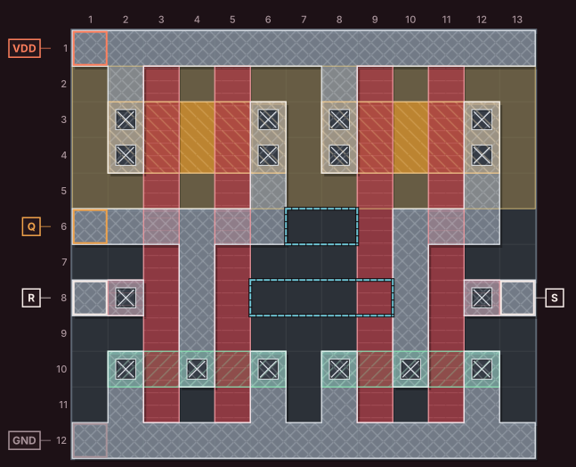
  • Part of the drawing is in place when the puzzle opens. To finish it, paint 5 empty squares and change 1 drawn square.
  • It forms 8 transistors: 4 N transistors and 4 P transistors. Each one is a place where polysilicon crosses active silicon.
  • 18 contacts join metal to the polysilicon or active silicon under it.
Starting drawing for puzzle 69, A set and reset latch, on a numbered grid.
The drawing when the puzzle opens. The dashed outline marks the squares the solution changes.

After the puzzle

The checked sequence includes time after the control pulses end. Feedback can retain the state during that interval; the scope shows the behavior measured in this drawing.

Experiment: Feedback and hold

Before records your passing drawing. Break one feedback route between the gates without changing the supply or control inputs. Compare Q during the same recorded input sequence, especially after the pulses end. Restore Before to reconnect the route. The target and input sequence stay unchanged.

The experiment is optional. It does not change the puzzle target.